The process of building a motion simulator on a budget.
The process is time consuming and required a lot of trial and error to a point of building a protype simulator with 500mm home built and machined actuators. These where made from pipes from Home Depot, 3D printed actuators, aluminum rails that where using high strength adhesive that was aircraft grade and machined aluminum threaded supports. Took months of trail and error and lots of testing to get to a working platform. The process below was what was first what I was shooting for but as you will see the design to the final unit changed drastically.
I was thinking of using two short throw projectors mounted on the top and use some form of open source software to stich the two images together in the middle. Instead home built actuators I was going to use torque converters and some form of rotational hardware that would move the platform up and down. After days of research I decided to go with 500mm ballscrews instead with linear actuators with mounting hardware yet designed.
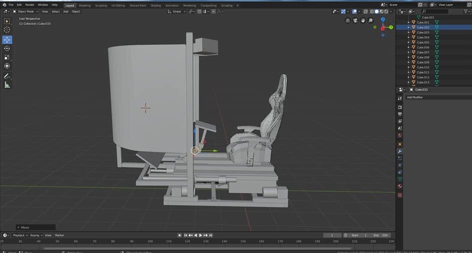
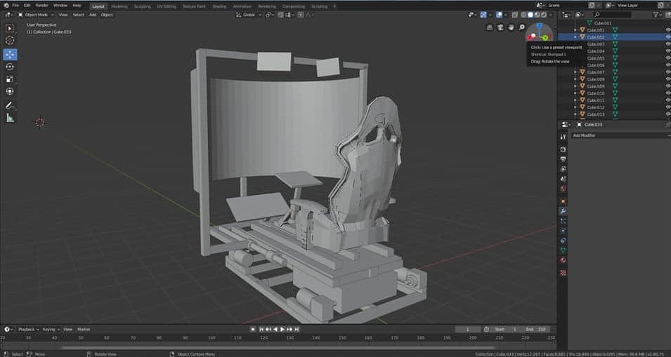
At this point below I started to work on the platform and how to mount the seat below is the progress on the platform and the keyboard that could be moved around via a modified TV holder mounted to the one of the TV supports.
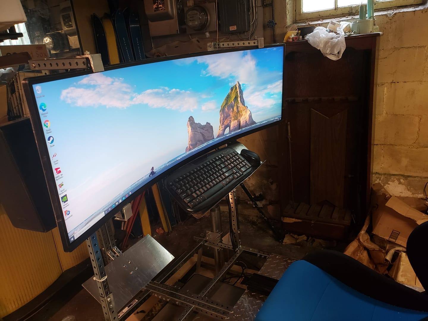
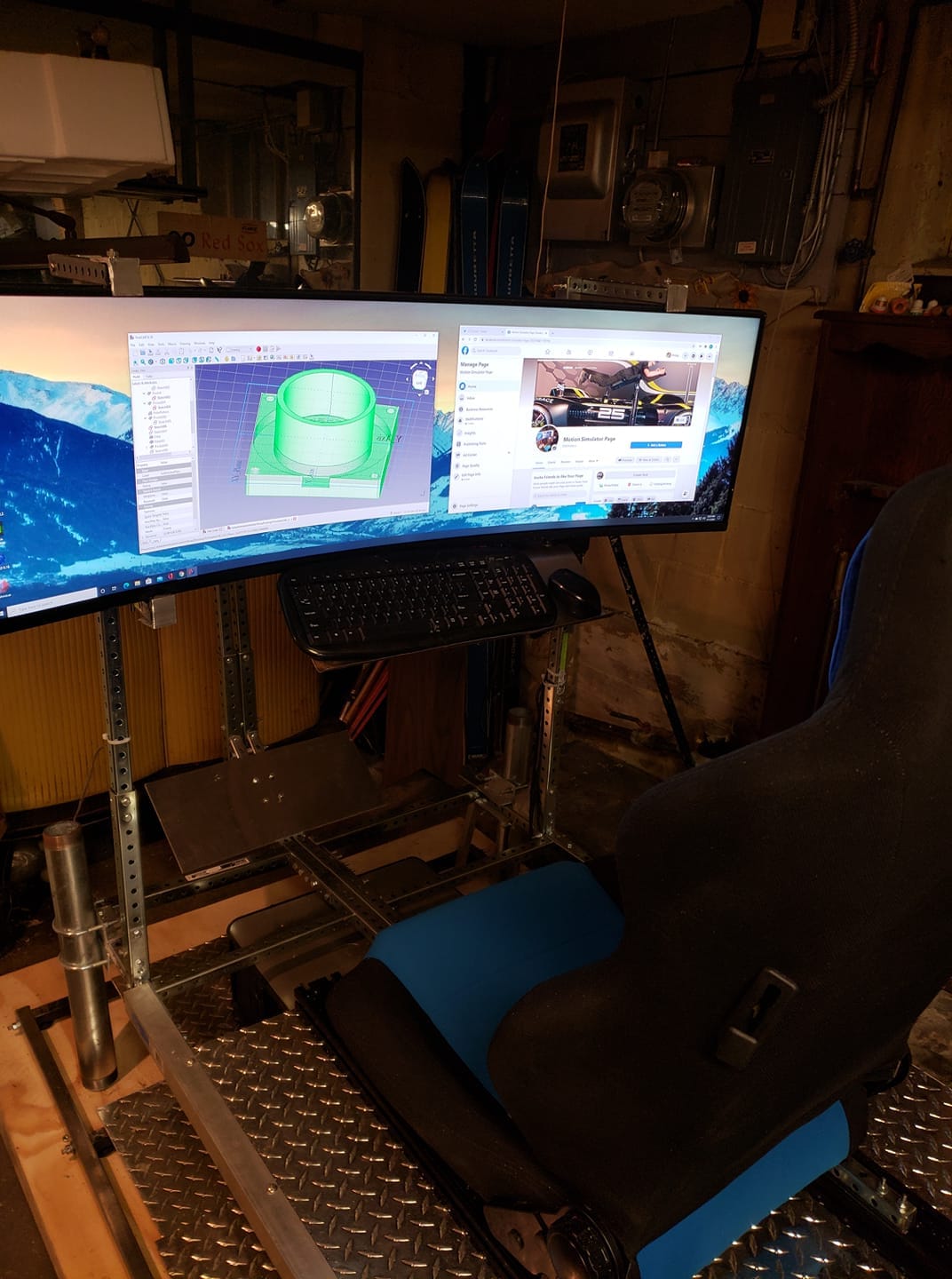
Lets just say the platform and the seat rails would very stressful as there is a ton of hardware below supporting the seat and extrusion rails. Up to this point I had no idea how I was going to run the actuators through the converted water pipes with0out welding inside smooth pipe. The bottom platform was 1 inch square steel tubing to hold the computer and the amplifier. You can see what would end up being the top and bottom 3D printed version of the actuator supports. They where first 3D printed then ended up getting them machined.
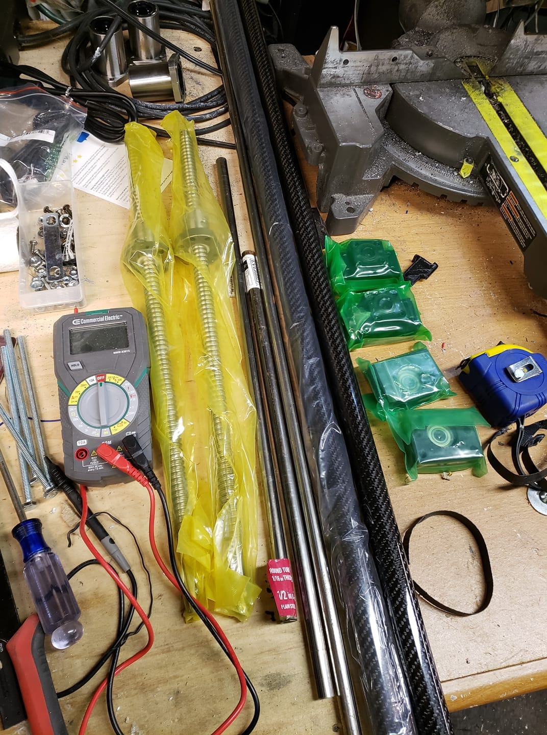
Above is the parts I would use to make two actuators as the carbon fiber I decided to use because it was light weight low friction to remove the bearings rings. Worked great next to low wear and very low noise as the bearing rings make more noise. You see in the photo the 5oomm ballscrews two of them the tubing for spacing the top and bottom machined aluminum supports. They hold the linear actuators and speakers.
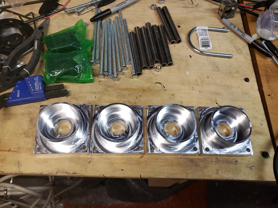
Above the final machined linear actuator supports and the steel pipe holder that I received to build my actuators. Took about a month to receive them and I still had no idea how well they would fit lol. I had not threaded the insides yet that would be done manually.
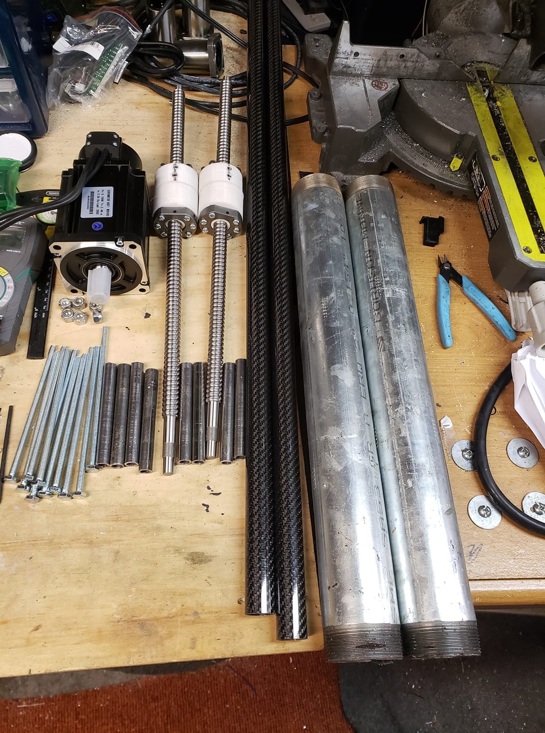
Things are starting to come together now my linear servo photographed with my actuator parts. Included in the photo is my 3D printed guides that are on the 500mm ballscrews. That would take a few days for the glue to harden regular high pressure glues did not work well on the steel pipe.
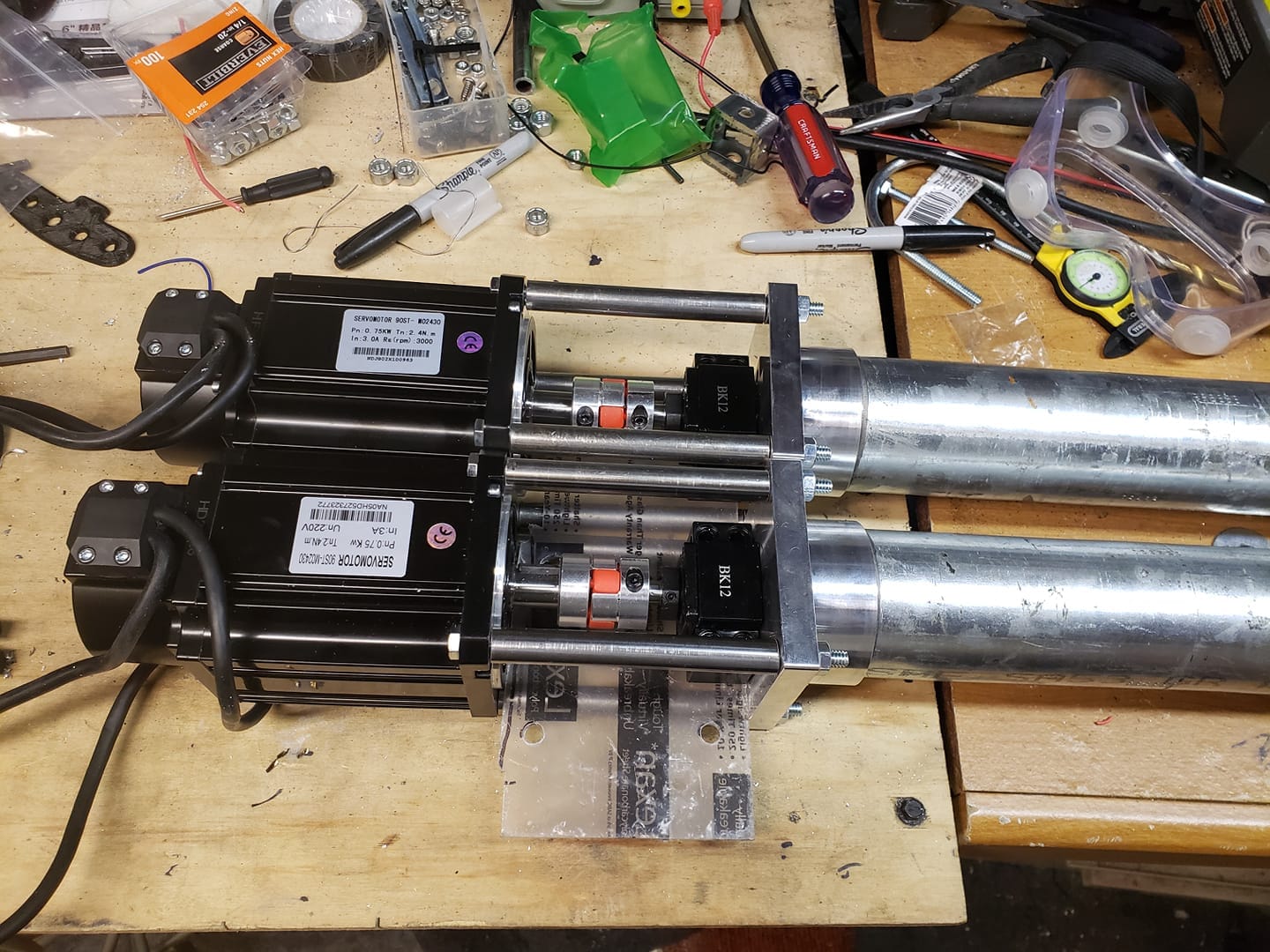
Photo above as things are starting to shape up as far as the actuators go. In the photo you see the only 2.4 nm actuators mounted to the interconnect to the pipe. Inside is the low cost interconnect to tie the linear servo to the ball screw and the mount.
Will continue it in the morning time to go to bed in the meantime here are some videos of it running in various stages.